1. System overview
How FlyPad measures feeding
Each fly sits in its own small chamber (arena) with two food sources. Every food source rests on a capacitive sensor made of two electrodes:
- the fly stands on the outer ring electrode;
- the food sits on the inner electrode.
When the fly touches the food with its proboscis or a leg, the capacitance between the two electrodes changes. Every contact appears as a sharp step in the signal. Each sensor is read 100 times per second (100 Hz) with femtofarad sensitivity, so single sips can be detected automatically. In the original validation against video, 92.5 % of manually scored sips were detected (Itskov et al., 2014).
From the sips, the analysis derives the feeding microstructure:
| Measure | Meaning |
|---|---|
| Sips | Individual contacts with the food; the number of sips is a proxy for intake |
| Sip duration | Length of each contact |
| Inter-sip interval (ISI) | Time between consecutive sips |
| Feeding burst | A period of uninterrupted feeding at the frequency of the feeding CPG (central pattern generator), with at least 3 sips |
| Activity bout | A period of sustained interaction with one food source |
| Preference index (PI) | (sips on A − sips on B) / (sips on A + sips on B), from +1 to −1 |
System components
| Component | Role |
|---|---|
| FlyPad basestation (Feeding Multiplexor) | Reads all sensors and streams the data to the PC over one USB cable |
| Arena modules | Four fly chambers per module; each chamber has two food sensors (8 channels per module) |
| OptoPad (optional) | LED boards for optogenetic stimulation, driven in real time by feeding (closed loop) or by a timed schedule (open loop). Each OptoPad consists of 3 LED boards and 1 controller board |
| Camera (optional) | An industrial USB3 or GigE Vision camera above the arenas: synchronised video and fly tracking |
| FlyPad Acquisition | The PC program: recording, live view, video and tracking, OptoPad control, review and analysis |
Channel layout
Each fly chamber has two channels, one per food source. Channel 1 and channel 2 belong to fly 1, channels 3 and 4 to fly 2, and so on:
- odd channels (1, 3, 5, …) = the left food = Substrate 1;
- even channels (2, 4, 6, …) = the right food = Substrate 2.
| System | Arena modules | Flies | Channels |
|---|---|---|---|
| Current FlyPad | up to 12 (P1–P12) | 48 | 96 |
| Earlier FlyPad | up to 8 (P1–P8) | 32 | 64 |
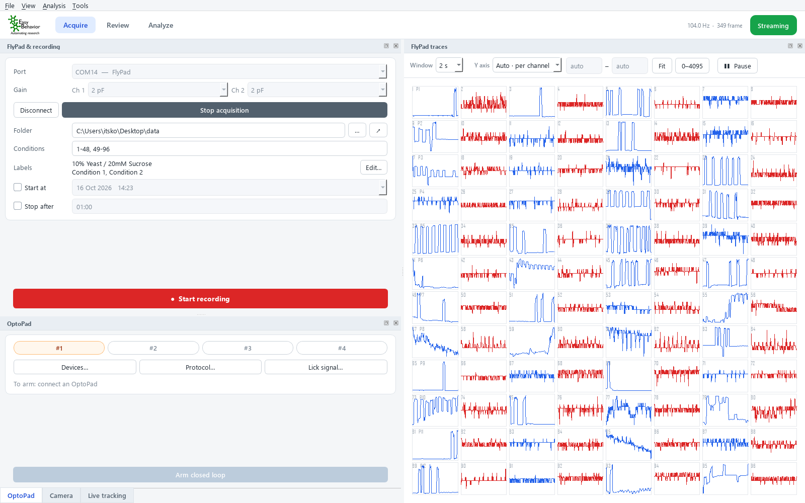
In the live view, each row of 8 channels is one arena module, labelled P1, P2, … at the left of the row. Blue traces are odd (left-food) channels, red traces are even (right-food) channels.
Recordings of both systems use the same file format. FlyPad Acquisition can review and analyse either.